

Reliable Centrifugal Compressor Selection for Continuous Industrial Operations
2026-08-24
Choosing a centrifugal compressor that won't let you down in a 24/7 plant is harder than most catalogs suggest. A single misstep in selection—wrong flow range, inadequate sealing, or poor turndown—can turn a critical process line into a bottleneck. At Seize Air, we've seen how the right sizing and materials decisions separate years of smooth operation from constant emergency calls. This guide walks through the factors that actually matter when reliability is non-negotiable.
Reading the Process Curve Before Picking Frame Size
A process curve offers a far more reliable basis for frame sizing than a single peak-power figure. By tracing how torque and speed fluctuate during a typical cycle, you can spot where the motor actually spends most of its time — and where it only visits briefly. That distinction matters because a frame that handles a brief overload may still overheat if the continuous operating point sits too close to its thermal limit.
When reading the curve, pay attention to the shape, not just the extremes. Flat sections indicate steady-state work, while sharp spikes reveal startup surges or intermittent tool engagement. A frame that only meets the average value will struggle with those spikes. Look for the portion of the curve that stays above 80 percent of rated torque for more than a few seconds; that is where a larger frame size earns its keep, even if it seems oversized on paper.
Finally, compare the process curve against the candidate frame's safe operating area, including derating for ambient temperature or altitude. Leave a practical margin — typically 10 to 15 percent — between the curve's maximum continuous requirement and the frame's continuous rating. This avoids forced cooling upgrades later and keeps the system stable when the process drifts slightly from its nominal profile.
Why Impeller Tip Speed Limits Shift With Molecular Weight
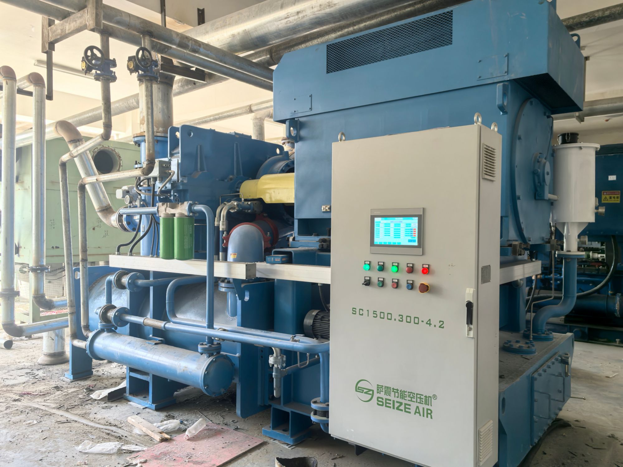
Compressor designers often treat impeller tip speed as a fixed ceiling until they start working with gases outside the typical air range. The actual constraint isn't velocity alone but the Mach number at the blade tip, which ties directly to the speed of sound in the working fluid. Since sound speed drops as molecular weight rises, a gas like propane or carbon dioxide reaches the same tip Mach number at a considerably lower absolute tip speed than hydrogen or methane. That means a stage originally rated for a light gas can't simply be repurposed for a heavier one without cutting the rotational speed or redesigning the impeller geometry.
The shift becomes even more pronounced when you account for compressibility effects. Heavier molecules carry more momentum per particle at a given velocity, so shock formation and flow separation at the inducer start earlier relative to tip speed. What looks like a conservative limit for nitrogen might be dangerously aggressive for a high-molecular-weight hydrocarbon. Experienced engineers keep separate tip speed curves for different molecular weights rather than applying a single number, because the margin between efficient operation and choke shrinks quickly as the gas gets heavier.
In practice, this means molecular weight forces a trade-off between head per stage and rotor diameter. A lighter gas can tolerate a larger diameter or higher rpm before hitting the same aerodynamic limit, while a heavier gas demands either a smaller impeller or a lower shaft speed to stay below the same tip Mach number. That's why equipment datasheets often specify tip speed limits as a function of molecular weight rather than as a single universal value.
Seal Gas Panels That Tolerate Dirty Hydrogen Better Than Textbook Designs
Most seal gas panel designs assume a clean, dry hydrogen stream straight from a textbook. Real plants rarely offer that luxury. Hydrogen recovered from refinery off-gases or produced by electrolysis often carries traces of moisture, sulfur compounds, or even particulate carryover. These impurities slowly degrade conventional filter elements and can cause sticky valve seats or worn sealing faces. A panel built for dirty hydrogen doesn't just add more filtration; it rethinks the flow path so that contaminants settle out harmlessly before reaching critical control points.
One practical upgrade is to position a knockout drum or coalescing stage ahead of the primary pressure regulation. In hydrogen service, small droplets of compressor lube oil or water are common, and they tend to blind standard sintered filters quickly. By allowing the gas to slow down and impinge on a series of baffles, you can pull out the bulk liquids without relying solely on disposable elements. The result is less frequent filter changes and fewer pressure drops across the panel during high-demand periods. Pair this with oversized sensing lines that resist plugging, and the panel keeps responding smoothly even when the hydrogen is far from pure.
Another difference shows up in materials and sealing choices. Textbook designs might specify standard elastomers or PTFE seats that work fine in a lab but harden or swell when exposed to trace amines or chlorides in field gas. Upgrading to perfluoroelastomer seals and using hardened trim on regulator stems can extend service life significantly. Some operators also add a simple bypass loop with a manual scrubber pot so that during upsets the panel can keep running on partially treated hydrogen without tripping the compressor. It's not about reinventing the seal gas panel; it's about admitting that real hydrogen is never perfect and designing accordingly.
Bearing Metal Temperature as a Leading Indicator of Misalignment
In many rotating machines, bearing metal temperature often tells a clearer story than vibration alone when shafts start to drift out of alignment. As misalignment grows, the load zone within the bearing shifts and narrows, forcing the oil film to work harder in a smaller area. That local squeeze generates heat almost immediately, long before the rotor develops enough force to show up as a noticeable vibration change. Operators who watch the bearing metal temperature trend—not just the absolute value—can spot a slow rise of a few degrees that tracks increasing misalignment, sometimes weeks before other symptoms emerge.
The reason this works lies in how misalignment changes lubrication. A properly aligned shaft spreads its load across a wide arc of the bearing, keeping oil film pressure moderate and metal temperatures stable. But when alignment degrades, the load concentrates near one edge or corner of the bearing shell. The oil film thins there, friction rises, and the babbitt metal heats up. A pair of embedded thermocouples or RTDs, placed at the likely hot spots, can reveal a growing temperature difference between the loaded and unloaded sides of the bearing. That differential often climbs more reliably than a single point temperature and gives maintenance crews a direct clue about the direction and severity of the misalignment.
Using bearing metal temperature this way requires a shift in thinking: instead of waiting for alarm thresholds, teams track small, consistent trends. A sudden jump of ten degrees may be too late, but a steady two- or three-degree rise over a month, combined with stable operating conditions, is a strong leading indicator. When that temperature climb is seen alongside slight changes in bearing oil pressure or unusual axial position, the case for realignment becomes compelling. In practice, plants that log bearing temperatures once per shift and compare them against known baselines often catch misalignment early enough to schedule a simple shim correction rather than a full bearing replacement.
When Over-Cooling the Interstage Gas Invites Condensation Damage
Bringing the interstage gas temperature down too far might seem like an easy win for efficiency, but it quietly sets the stage for moisture to drop out of the vapor. Once the gas dips below its dew point, liquid water forms inside the piping and cooler passages. That water then gets swept into the next compression stage, where it slams against impeller blades at high velocity, causing erosion that starts as small pits and eventually grows into serious surface fatigue.
The damage isn't limited to mechanical wear. Condensed water often absorbs trace acids or other corrosive compounds from the gas stream, turning into a mildly aggressive fluid that attacks seals, bearings, and internal coatings. In colder ambient conditions, the same moisture can freeze and block narrow passages, leading to uneven flow distribution and unexpected vibration. Operators sometimes overlook these risks because the initial performance numbers look perfectly normal.
A safer approach is to keep the interstage cooling target just above the calculated dew point, with a margin that accounts for variations in gas composition and inlet conditions. Installing high-efficiency moisture separators and automatic drain traps right after the cooler helps remove any condensate that still forms during transient operation. Periodic checks of the gas analysis and cooler outlet temperature can reveal when ambient changes or fluctuating feed gas quality push the system toward the condensation zone, allowing adjustments before real damage takes hold.
Testing Surge Margin With Real Valve Dynamics Instead of Static Maps
Static surge margin maps assume a fixed relationship between valve position, flow, and pressure ratio, but real antisurge valves never behave that way. Actuator stroke time, friction, position overshoot, and supply pressure variations all shift the effective valve opening during a transient. Relying on a static map can hide a dangerously small surge margin during fast disturbances or, just as often, force the control system to open the recycle valve more than necessary, wasting energy.
A more revealing method is to run surge margin tests with the actual valve dynamics in the loop. The compressor is brought close to its surge line while the antisurge valve receives realistic command sequences—steps, ramps, and simulated process upsets. Fast-response pressure transducers and valve position feedback are logged at high frequency, so the measured surge margin reflects the true lag between commanded and delivered flow, not an idealized curve.
The difference can be striking. Some compressors show a 3–5% reduction in usable surge margin compared to the static map prediction, while others gain margin because the valve is faster than assumed. Either way, feeding these results back into the surge control tuning leads to protection that matches the machine's real behavior, often allowing tighter operation without crossing into surge.
FAQ
You need the full range of suction and discharge pressures, temperatures, gas composition, and expected flow turndown. Site altitude, ambient conditions, and utility limits also matter because they directly affect performance calculations.
Gas composition can shift with process upsets or feedstock changes. I usually ask for worst-case molecular weight and specific heat ratio scenarios, then check that the selected compressor can handle both the lightest and heaviest gas without exceeding rotor stability limits or driver power.
Impellers with backward-leaning blades and appropriate flow coefficients give a wider stable operating range. That matters in continuous plants because you don't want the compressor to hit surge or choke when the process load changes slightly. A conservative impeller selection reduces the chance of trips.
Dry gas seals eliminate the seal oil system and are generally more dependable for continuous service, but they require clean, dry buffer gas. If the process gas contains solids or liquids, you have to add effective filtration and knockout upstream. Otherwise seal failures become the most common forced outage.
You should size the compressor so the normal operating point sits well away from the predicted surge line at minimum flow. Using variable inlet guide vanes instead of a simple throttle valve can extend turndown without wasting energy. If turndown is extreme, multiple compressor bodies or speed control may be needed.
For wet CO2 or H2S service, austenitic stainless steels or duplex stainless steels are often used for casings and impellers. In highly corrosive environments, nickel-based alloys may be required for rotating parts. The exact choice depends on chloride content, pH, and operating temperature, so a materials engineer should review the process data early.
A mechanical running test verifies vibration levels, bearing temperatures, and seal performance at full speed. A performance test per ASME PTC 10 confirms head, flow, and power against the datasheet. For critical continuous units, a full-load test with the actual driver is worth the extra cost because it catches alignment and torsional issues before installation.
Continuous vibration monitoring with proximity probes on each bearing, along with performance monitoring of flow, pressure, and discharge temperature, gives early warning of fouling, seal wear, or impeller damage. Trending this data lets you plan maintenance during scheduled turnarounds instead of reacting to unplanned failures.
Conclusion
Reliable centrifugal compressor selection for continuous industrial operations starts with reading the process curve before choosing frame size. A machine that looks properly sized on paper can operate too close to surge or stonewall if the expected flow and head variations are not mapped against the actual curve. Impeller tip speed limits are not fixed values; they shift with molecular weight, so a gas composition change from natural gas to a hydrogen-rich stream may require derating or a different impeller trim to avoid excessive stresses. Seal gas panels are another area where textbook designs fall short, especially with dirty hydrogen. Panels that tolerate particulates and moisture without plugging small orifices and filters are essential for long runs.
Bearing metal temperature serves as a leading indicator of misalignment, often showing a slow upward trend before vibration becomes obvious. Monitoring this parameter at constant load helps maintenance teams correct alignment before a forced outage. Interstage cooling must be controlled carefully, because over-cooling can bring the gas below its dew point and invite condensation erosion or corrosion damage on downstream components. Surge margin validation should also move away from static maps and use real valve dynamics instead. Testing recycle or blow-off valves under actual opening and closing speeds reveals transient dips in surge margin that a static curve cannot predict, giving operators confidence in continuous operation.
Contact Us
Contact Person: Mia
Email: [email protected]
Tel/WhatsApp: +86 19821985894
Website: https://www.seize-air.com