

Mold Steel Manufacturing Techniques for High-Performance Tooling
2026-08-17
Precision tooling demands more than just good steel—it demands the right manufacturing techniques. In high-performance applications, from injection molds to die casting, the way mold steel is produced directly determines tool life, surface finish, and dimensional stability. Yet many engineers overlook the critical processes behind the material itself. At Jiangsu Baowu New Materials, we believe understanding these techniques is the first step toward smarter tooling decisions. This blog breaks down the essential mold steel manufacturing methods that separate reliable, high-performance tooling from costly trial-and-error.
Selecting Mold Steel by Failure Mode, Not Just Application
Most mold buyers start with a simple question: what steel works for this part? That's backwards. The real question is what failure you're trying to prevent. Cracking, wear, corrosion, thermal fatigue, or dimensional drift each demand a different metallurgical strategy. A steel that excels in a high-wear gate area may fail miserably in a water-line zone prone to stress corrosion. Ignoring failure mode means you're optimizing for the wrong threat.
Think of it as triage. If your cores are washing out from abrasive fillers, you need high surface hardness and maybe a powder metallurgy grade. If the failure is heat checking on a die-casting tool, you need toughness and thermal conductivity more than raw hardness. If the problem is pitting from PVC off-gassing, a stainless or high-chromium tool steel makes sense. Each failure signature points to a different material property, and often a different heat treatment.
The practical approach is to map the tool's failure history before ordering steel. Look at the actual cracked, worn, or corroded inserts. Document where and how they failed. Then reverse-engineer the material requirements. This might mean using a tougher H13 variant instead of a harder D2, or a maraging steel for a thin wall section that keeps snapping. Application tells you what the mold does; failure mode tells you what the steel must survive.
Vacuum Hardening and the Hidden Cost of Distortion
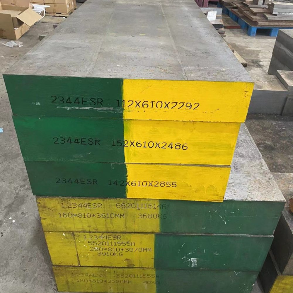
Vacuum hardening promises clean, scale-free surfaces and minimal decarburization, but the real expense often hides in the geometry you get back. When a part leaves the furnace, it carries residual stresses that don't show up on a hardness printout. These internal tensions quietly wait until the first cut, the first assembly torque, or the first thermal cycle before revealing themselves as warpage, twist, or out-of-round conditions. The tool that looked perfect on the bench suddenly doesn't seat, the gear that passed final inspection now whines under load, and the mold that fit the press yesterday now binds on the guide pins.
What's rarely discussed is how vacuum processing can amplify distortion because the cooling is so uniform yet so rapid. Unlike oil quenching, where the vapor blanket and convection stages create a somewhat forgiving thermal gradient, high-pressure gas quenching in vacuum hits every surface almost simultaneously. The core cools more slowly than the case, setting up a tug-of-war between contraction rates. Thin sections pull away from thick bosses, long slender shafts bow toward the quench flow, and asymmetric features like keyways or cross-holes become stress risers that dictate where the part will move. You don't see this in the furnace chart, but you will see it when the CMM report lands on your desk.
Ignoring distortion means paying for it later in straightening, hard machining, or scrapped lots. A shop that tracks true cost per conforming part quickly learns that a cheaper vacuum cycle can become the most expensive one if it leaves you with a basket of bananas instead of bearing journals. The hidden cost isn't in the hardening price at all—it's in the hours spent compensating, the fixtures built to force-fit warped parts, and the field failures that trace back to a stressed microstructure nobody measured. Smart processors treat distortion as a design input, not an afterthought, adjusting quench pressure, fixturing, and even part orientation before the first heat. That's where the real savings live.
High-Feed Milling Strategies That Preserve the Steel Surface
High-feed milling shifts the cutting force mostly into the axial direction by keeping the depth of cut small and pushing feed per tooth high. On steel workpieces this matters because lateral deflection and chatter quickly translate into visible witness marks. Keeping the cutter engaged with a steady chip load, rather than letting it dwell at corners or plunge into sharp transitions, helps the surface stay clean without secondary finishing passes.
Toolpath selection has an outsized effect on surface integrity. Helical entries, trochoidal loops around tight pockets, and roll-in/roll-out arcs at the end of each pass prevent the abrupt load changes that tear the top layer of steel. A light mist or air blast is often better than flooding the cut with coolant, since it avoids thermal shock while still evacuating chips so they do not get re-cut into the surface.
For steel surfaces that need to remain untouched after roughing, the tool itself deserves attention. Small corner radii or wiper flats spread the final contact over a wider edge, reducing the ridge height between passes. Programming feed rates to stay constant through arcs, and avoiding any pause or reversal on the finished wall, keeps the metal from being work-hardened in patches that later show up as dull bands.
Plasma Nitriding for Complex Mold Geometries
Plasma nitriding brings a level of control that conventional gas or salt bath methods simply cannot match when a mold cavity twists, narrows, or hides behind deep ribs. Because the glow discharge envelops the entire exposed surface, nitrogen ions are drawn into recessed areas, undercuts, and fine details that would otherwise shield themselves from a flowing atmosphere. This means a complex geometry receives a relatively uniform case depth without the need for elaborate fixturing or auxiliary anodes.
The process also sidesteps a common headache: dimensional movement. Complex molds often carry tight tolerances, and any post-treatment grinding can destroy the very accuracy that took days to machine. Plasma nitriding operates at lower temperatures, typically between 450°C and 580°C, and the hard compound layer forms by diffusion rather than by adding a thick coating. As a result, sharp edges stay sharp, deep cavities keep their shape, and the risk of distortion drops dramatically.
Beyond uniformity, the technique lets a mold shop tune the surface metallurgy for each region of a tool. By adjusting gas mixtures, pressure, and pulse timing, one can suppress the brittle white layer on high-impact corners or promote a thicker nitride zone where abrasive flow erodes a gate or vent. That kind of local control, applied to a convoluted parting line or a textured cavity floor, is what keeps complex molds running longer between polishing stops and insert replacements.
Detecting Inclusions Before They Become Surface Defects
Subsurface inclusions rarely announce themselves. They sit quietly inside the casting or rolled slab, invisible to the naked eye, until a later forming step stretches the material just enough to pull that hidden weakness to the surface. By the time a crack opens or a sliver peels away, the part has already cost time, tooling, and often a customer's patience.
The practical challenge is catching these inclusions while they are still buried. Ultrasonic testing, eddy current, and high-frequency magnetic methods each have a window of depth and material sensitivity, but none of them work well if the inspection is treated as a final sorting gate. The earlier the check is moved into the process, the better the chance of finding a small oxide film or refractory fragment before rolling, forging, or machining turns it into an open defect.
That shift in timing changes the definition of a good inspection. Instead of looking for a finished surface blemish, inspectors look for velocity shifts, impedance changes, or faint backscatter that suggest something is there but not yet visible. It is slower work in setup, and it asks more from the people reading the signals, but it is far less expensive than discovering the same inclusion after a customer has cut into the part.
Balancing Toughness and Hardness in High-Impact Molds
High-impact molds face a constant tug-of-war between toughness and hardness. Hardness resists surface wear and keeps edges sharp, but too much of it makes the steel brittle under repeated shock. Toughness absorbs impact without cracking, yet an overly tough grade can deform or gall in high-pressure areas. The trick lies in knowing which zones of the mold need which property, rather than chasing a single all-round number.
Many toolrooms default to a middle-ground hardness like 48-52 HRC and call it balanced. In practice, that often means mediocre performance at both ends. A better approach is selective processing: through-hardening the core to a moderate level, then applying nitriding or induction hardening only where flash, wear, or tight shutoffs occur. This way, the bulk of the mold retains its impact resistance, while critical surfaces get the extra hardness they actually need.
Material choice also plays a bigger role than chasing a magic hardness spec. Modified H13 or premium ESR grades with cleaner microstructures handle impact far better at the same hardness than standard stock. Combined with proper stress relief and double tempering, it is possible to run a mold at 50 HRC that outlasts a cheaper steel at 46 HRC. The goal is not to pick a number off a chart—it is to understand where the shock loads concentrate and design the heat treatment around that reality.
FAQ
High-performance mold steels are formulated with tighter control over alloy content and inclusion levels. They also undergo specialized remelting or refining steps, which results in fewer microstructural defects and better polishability, thermal fatigue resistance, and dimensional stability under repeated heating and cooling cycles.
Vacuum degassing pulls dissolved gases like hydrogen and oxygen out of the molten steel, reducing porosity and the risk of hydrogen-induced cracking. It also lowers non-metallic inclusion counts, so the finished tool is less likely to fail from fatigue or stress corrosion during demanding production runs.
Electro-slag remelting gives a more uniform, fine-grained structure with very low sulfur and inclusion content. This translates into better toughness, improved polishing response, and consistent hardness across large blocks—qualities that matter when a mold must survive thousands of cycles without surface degradation.
Heat treatment sets the final matrix structure—usually tempered martensite with fine carbides—so you can hit the exact hardness, toughness, and dimensional stability needed for a given tool. Done well, it also relieves residual stresses from prior machining and reduces the chance of distortion during service.
Chromium provides hardenability and corrosion resistance, molybdenum improves high-temperature strength and resists tempering, and vanadium forms fine carbides that boost wear resistance. The proportions are adjusted depending on whether the tool will face abrasive plastics, corrosive polymers, or high-pressure die casting.
Powder metallurgy solidifies the steel from tiny droplets, which prevents the segregation of alloying elements and produces an extremely uniform carbide distribution. That means you can use higher alloy contents without losing toughness, and the resulting steel takes a better polish and holds fine details longer.
Nitriding, PVD coatings like TiN or CrN, and sometimes hard chrome plating are used to create a hard, low-friction surface layer. These treatments reduce adhesive wear and corrosion, especially in high-volume injection molding, while leaving the core tough enough to absorb mechanical shock.
They control solidification speed, use multi-directional forging or rolling, and carefully manage cooling after hot working. This breaks up coarse as-cast structures and distributes carbides evenly, preventing soft spots or anisotropic properties that could cause localized failures in a large tool.
Conclusion
Choosing mold steel strictly by application often misses the real driver: how the tool actually fails. Cracking, wear, thermal fatigue, or plastic deformation each point to a different material property, so it pays to rank failure modes before locking in a grade. Vacuum hardening remains the standard for clean, oxidation-free results, but the real expense shows up later in distortion and the extra grinding or EDM work needed to bring a complex cavity back to tolerance. Better control of quench rate and fixture design often cuts more cost than chasing a marginally higher hardness. In parallel, ultrasonic and microscopic inclusion checks on incoming bar stock can stop a near-finished mold from being scrapped because a tiny non-metallic stringer opened up at the parting line or on a polished rib face.
Machining and surface treatment decisions are equally tied to tool life. High-feed milling with a small depth of cut and heavy chip thinning preserves the steel's subsurface integrity, avoiding the white layer and micro-cracks that later show up as pitting or premature fatigue on textured mold faces. For complex geometries, plasma nitriding is more forgiving than gas or salt bath processes because it uses lower temperatures and can be masked locally, so you get a hard diffusion case on ribs, deep pockets, and slides without redesigning the entire heat treatment sequence. The trade-off between toughness and hardness in high-impact molds is rarely solved by a single number; adjusting tempering temperature after vacuum hardening, or specifying a double-tempered grade, often gives the best balance. When all these steps are treated as one chain rather than isolated operations, the result is a tool that holds dimension, resists wear, and survives the occasional process upset.
Contact Us
Contact Person: Zoe Liang
Email: [email protected]
Tel/WhatsApp: 86 189 2128 6299
Website: https://www.baowuchina.com