
Megasonic Wafer Cleaning System Factory: Precision Cleaning for High-Yield Semiconductor Production
2026-10-28
In the high-stakes world of semiconductor manufacturing, even the smallest particle can kill a chip. As device geometries shrink and yields become the ultimate battleground, wafer cleaning has evolved from a routine step to a precision science. Enter Siansonic, a megasonic wafer cleaning system factory that doesn't just remove contaminants—it redefines what clean really means. Here’s why high-yield fabs are paying closer attention.
How Acoustic Energy Lifts Particles Without Touching the Wafer
Particles cling to wafer surfaces through a stubborn mix of van der Waals, capillary, and electrostatic forces. A brush or chemical cleaner might break those bonds, but it also risks scratching delicate features. Acoustic energy takes a different route. A transducer emits high-frequency sound waves into a thin liquid layer above the wafer. When those waves bounce back from the solid surface, they interfere and form a standing wave pattern. Tiny particles caught in this field feel a radiation pressure that pushes them toward low-pressure nodes, lifting them just off the wafer without any physical contact.
The trick lies in how the particles respond differently from the surrounding fluid. Because their density and compressibility contrast with the liquid, the acoustic gradient exerts a net force on them. At ultrasonic frequencies, this force easily overcomes the adhesive pull holding particles down. Once suspended a few micrometers above the wafer, they drift into a slow-moving liquid stream and are carried away. The wafer itself stays untouched, which means fewer scratches, less chemical waste, and no abrasive pad wear.
Tuning the standing wave gives precise control over where the lifting happens. Systems typically operate in the megahertz range to produce closely spaced nodes, which is just right for sub-micron particles. The cleaning zone can be focused on patterned structures without disturbing adjacent areas. It is a surprisingly gentle yet effective way to remove contamination, using nothing but focused acoustic energy to break the contact and let the particles float free.
Factory Calibration Runs That Replicate Cleanroom Conditions
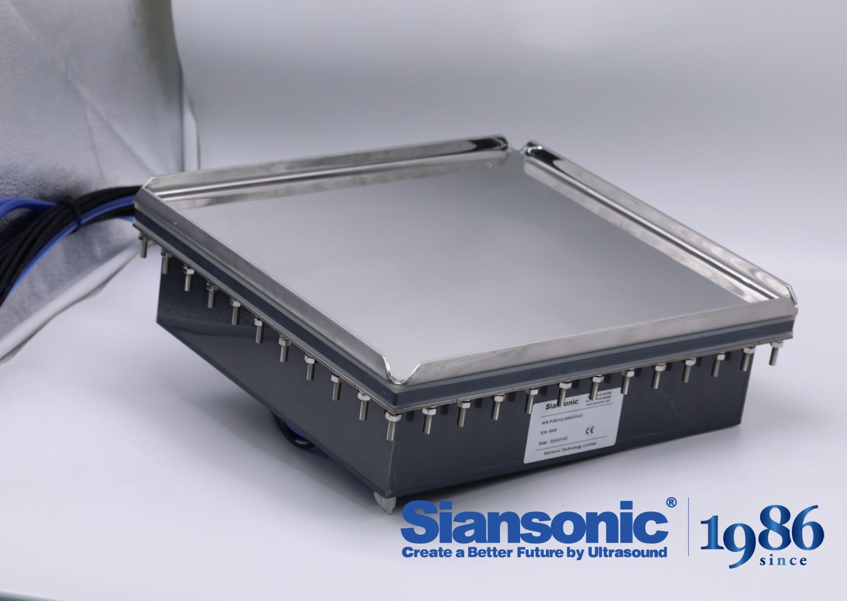
Every calibration cycle in our facility begins with a deliberate reset of the ambient environment, not just the equipment. Air handlers are switched to a dedicated filtration loop that pulls particulate counts down to the same ISO Class 5 thresholds used in customer cleanrooms. This means the sensor drift you might see in a standard factory bay simply doesn't exist here—our calibration benches sit inside positive-pressure enclosures with HEPA-filtered laminar flow, so every optical particle counter or air sampler is challenged against reference standards in air that matches its intended operating space.
Temperature and humidity are locked to a narrow band, typically 21 ± 0.5 °C and 45 ± 3 % RH, monitored continuously rather than spot-checked. We use chilled mirror hygrometers as the primary reference, not digital sensors, because they provide a physical dew point that isn't subject to electronic drift. Vibration isolation pads under each calibration station absorb low-frequency noise from nearby HVAC equipment, which matters more than most people realize when you're trying to hold a 0.1 µm particle size standard steady for a thirty-minute sampling cycle.
What sets these runs apart is the data trail. Instead of a simple pass/fail stamp, we record a time-series of environmental parameters—particle counts at 0.3 µm and 0.5 µm, temperature, humidity, and differential pressure—alongside the instrument's response. That lets our metrology team separate a genuine calibration shift from a temporary environmental hiccup. If the cleanroom conditions aren't met for the full duration of the run, the entire calibration is voided and rescheduled. No partial credit. No 'close enough.'
From Rinse Water Chemistry to Drying Without Streaks
The minerals hiding in rinse water—calcium, magnesium, silica—rarely announce themselves until the surface dries. As the water evaporates, those dissolved solids precipitate into white spots or hazy films that are maddeningly difficult to remove from glass, polished metal, or precision optics. Start by cutting total dissolved solids through deionization or reverse osmosis, but don't assume pure water alone fixes everything. Even low-TDS water can leave marks if the surface chemistry isn't right.
Surface tension is the silent accomplice. Rinse water beads up on hydrophobic or slightly contaminated surfaces, and as each bead dries, it concentrates whatever residue remains into a circular stain. Lowering surface tension with a small dose of a low-foaming, nonionic surfactant—or a short-chain alcohol like isopropanol for sensitive applications—encourages the water to sheet off uniformly instead of beading. The tricky part is balance: too little surfactant and droplets persist; too much and you trade water spots for a greasy or powdery film that's equally annoying.
Drying method can't be an afterthought. Air knives, heated forced air, or infrared panels speed evaporation, but if the rinse water hasn't been properly conditioned, faster drying simply bakes the residue into the surface. The most reliable approach is to pair low-TDS water with a carefully tuned wetting agent and a controlled drying zone—angled airflow, moderate heat, no stagnant pockets. When the final rinse sheet breaks cleanly without leaving isolated droplets, you've hit the sweet spot where chemistry and drying work together instead of fighting each other.
Yield Gains That Start With Pre-Diffusion Cleaning
Most growers treat pre-diffusion cleaning as an afterthought, but the numbers tell a different story. When extraction surfaces are free of residual sugars, gums, and fine particulate before the solvent ever touches the material, the diffusion gradient stays sharper for longer. That means less channeling, fewer stalled extractions, and a final yield that doesn't quietly bleed away into hidden dead zones. A quick rinse with the right solvent blend at ambient temperature can push recovery rates up by a measurable margin, without adding hours to the cycle.
The real hurdle isn't the cleaning itself—it's knowing what you're actually removing. Fresh feedstock often carries a thin film of surface wax and cell debris that isn't visible to the eye, yet it acts like a gasket once compacted. By integrating a low-pressure pre-wash with a short drainage pause, you give that film a chance to loosen and leave before the main solvent charge arrives. Operators who track this step consistently report fewer pressure spikes and a more uniform color in the collected extract, signs that the solvent is working on the intended solute rather than fighting through a clogged interface.
There's also a compounding effect that gets overlooked. Cleaner diffusion surfaces mean you can run slightly higher bed densities without sacrificing flow, which in turn reduces solvent-to-feed ratios. The gain isn't just in the first extraction—it shows up again in the second and third passes, because the remaining matrix stays more open and accessible. So before chasing ever-higher temperatures or longer soak times, it's worth taking a hard look at what a simple pre-diffusion cleaning step can do for the bottom line.
Customizing Transducer Arrays for Thin and Warped Wafers
Achieving uniform acoustic coupling on thin, warped wafers is rarely a matter of simply scaling down conventional transducer designs. The bow and topography introduced by residual stress or prior processing steps create localized standoff variations, so the array must be tuned to tolerate non-flat surfaces without sacrificing spatial resolution. This often means rethinking element spacing and kerf geometry to keep the focal zone consistent across the entire wafer, rather than optimizing for a single idealized plane.
One practical route is to segment the array into independently driven sub-arrays, each with its own delay compensation. By mapping the wafer's measured surface profile ahead of time, the excitation pattern can be adjusted so that the acoustic energy follows the actual topography. Paired with a conformable coupling layer or a vacuum-assisted chuck that flexes the wafer only minimally, this approach reduces the risk of edge cracking while still delivering enough energy to detect subsurface defects in warped regions.
Material choice for the array housing and backing also plays an outsize role. Rigid ceramic housings transfer stress into thin wafers during scanning, whereas a polymer composite frame with low thermal expansion can absorb mechanical mismatch and keep the elements aligned. In practice, customizing the transducer array for these wafers means treating flatness as a variable rather than a given—building in enough mechanical and electronic adaptability to inspect what is actually in front of the array, not a perfect reference wafer.
Monitoring Cavitation Stability Across Long Production Shifts
Cavitation rarely announces itself with a single event. On a twelve-hour line, the onset can creep in as bearing temperatures climb a few degrees, or as the discharge pressure trace picks up a ragged edge that wasn't there at handover. The real challenge is separating normal process noise from the early signature of vapour bubble collapse. Operators tend to rely on a mix of suction pressure readings, accelerometer data on the pump casing, and sometimes hydrophone signals if the budget allowed it. The trick is setting baselines per shift, not per machine, because the same pump behaves differently after lunch when tank levels drop and viscosity shifts with temperature.
Long runs expose a different kind of drift: sensor drift. A pressure transducer that was calibrated at 6 a.m. may read 0.2 bar low by the third shift, which is often enough to mask the pressure margin you thought you had. That’s why field teams pair continuous monitoring with spot checks, using handheld vibration meters and strobe lights to confirm what the online system suggests. If cavitation is suspected, one quick test is to throttle the discharge slightly and watch the high-frequency vibration band; genuine cavitation usually responds within seconds, while a loose bracket or worn bearing will not.
The goal across a long shift is not to eliminate every bubble, but to keep the cavitation zone stable enough that it doesn't eat impeller material or hammer seals. Some plants track a simple stability index: the standard deviation of the 5-10 kHz vibration envelope over rolling fifteen-minute windows. A rising trend that doesn't flatten out after a process adjustment is the signal to switch to a standby pump and inspect. Without that discipline, you're just waiting for a sudden drop in flow and an unscheduled teardown.
FAQ
Megasonic systems operate at frequencies around 800 kHz to 1 MHz, which creates gentle yet highly uniform acoustic streaming. That helps lift submicron particles off wafer surfaces without the cavitation damage you often see with lower-frequency ultrasonic baths.
The line combines controlled chemical delivery, DI water rinsing, and precisely tuned megasonic energy. Each wafer passes through a monitored process chamber where temperature, flow rate, and acoustic power stay within tight tolerances, reducing particle counts to levels that support stable device yields.
Yes. Because megasonic energy avoids violent bubble collapse, it is suitable for thin wafers, bonded stacks, and devices with fragile microstructures. The tool can adjust power density and scan speed to match wafer thickness and pattern sensitivity.
It removes slurry residues, organic films, metal ions, and submicron particles left after CMP, etch, or deposition steps. The combination of chemistry and acoustic force penetrates narrow trenches and high-aspect-ratio features more effectively than spray or brush cleaning alone.
Particle-related defects directly reduce die yield. By achieving consistent, damage-free removal of particles below 100 nm, the system lowers defect density on critical layers, which helps fabs maintain higher probe yields and reduces scrap.
Yes, the factory builds systems for 150 mm, 200 mm, and 300 mm wafers, and can integrate with existing wet benches or standalone platforms. Process recipes can be tailored for specific films, device nodes, and cleaning chemistries.
The equipment uses in-situ particle monitoring and automated calibration routines. Data logging tracks every wafer lot, so process drift is caught early, and maintenance intervals are triggered by actual performance rather than fixed schedules.
DI water serves as the coupling medium for acoustic energy and as a rinsing agent. It carries away loosened particles and prevents re-deposition, especially when combined with dilute chemistries and nitrogen-assisted drying after the megasonic step.
Conclusion
Inside a megasonic wafer cleaning system factory, the focus isn't simply on removing particles—it's on doing so without ever touching the wafer. Acoustic energy, delivered through precisely tuned transducers, creates controlled cavitation and microstreaming that lift contaminants from delicate surfaces. Before any system ships, it undergoes factory calibration runs that replicate cleanroom conditions down to residual particle counts and humidity levels. These runs validate that the cleaning performance matches what a high-yield fab expects on day one. The factory also pays close attention to rinse water chemistry and drying dynamics. By adjusting dissolved gas levels, pH, and surface tension modifiers, the equipment avoids streaking and watermark defects that would otherwise compromise lithography or diffusion steps.
A major part of the yield conversation happens before diffusion, where even nanometer-scale residues can ruin junction formation. That's why pre-diffusion cleaning has become a gatekeeper for overall fab productivity. Meanwhile, the factory handles the reality of thin and warped wafers by customizing transducer arrays—altering element spacing, power distribution, and frequency sweeps so that acoustic energy stays uniform across a bowed surface without creating stress fractures. On the production floor, operators monitor cavitation stability across long shifts using real-time acoustic emission sensors. These sensors flag subtle shifts in bubble dynamics that might go unnoticed but would still lead to particle re-deposition. The result is a cleaning system that maintains edge-to-edge consistency hour after hour, turning a support process into a measurable driver of semiconductor yield.
Contact Us
Contact Person: Ivy Zhang
Email: [email protected]
Tel/WhatsApp: +86 1081502288
Website: https://www.siansonic.com/