

China Test Connector Options Compared for High-Reliability Systems
2026-11-16
In high-reliability systems, a test connector is rarely the first component engineers discuss—but it is often the one that quietly decides whether a design passes validation or stalls on the bench. The choices have multiplied: cabled versus PCB-mounted, latching versus friction-fit, shielded versus unshielded, each promising robust signal integrity under stress. For teams designing into aerospace, automotive, medical, or industrial control environments, the real question is not which connector looks best on a datasheet, but which one can survive thousands of mating cycles, thermal swings, and vibration without introducing intermittent failures. This article compares China-based test connector options through the lens of those demanding conditions. As a manufacturer focused on precision interconnect solutions, REUNION has seen how subtle differences in contact geometry, housing material, and retention force separate dependable test points from costly troubleshooting later. We will break down the options side by side, so you can match the connector to the reliability your system actually requires—not just to the footprint that happens to be available.
What Datasheets Leave Out of High-Reliability Test Setups
Most datasheets give you a clean set of limits measured under narrow, well-behaved conditions. What they rarely show is how those limits drift when the part sits between hot regulators, fast digital return currents, and a slightly inductive ground plane. In high-reliability work, the missing data is not the headline number; it is the margin under combined stress. A comparator that looks stable on paper can pick up a few millivolts of offset from thermal gradients across the package, enough to shift a threshold in a circuit that has no second chance to re-trip.
Another gap shows up in transient behavior and fault recovery. A datasheet may promise overvoltage tolerance or short-circuit survival, but it seldom describes what happens after the stress is removed. Does the part return to the same reference, or does it carry a subtle parametric shift that only appears hours later? In high-reliability setups, that kind of silent degradation matters more than the initial failure, because it can pass a production test and then drift in the field. The only reliable way to close that gap is to characterize a small sample across the real operating envelope, including messy power-up sequences and brown-out corners.
There is also the problem of assumed cleanliness. Datasheets imply a certain amount of decoupling, grounding, and layout discipline, but they rarely quantify how much the part's own switching noise couples into nearby high-impedance nodes. In a tightly packed, high-reliability assembly, a tiny bit of crosstalk can look like a real signal. Building a test setup only to the datasheet numbers often means you are proving the part works in a world that does not exist. Real confidence comes from measuring the circuit with the same cabling, shields, and ground paths as the final installation, and then pushing the conditions well past the stated maximums to see where the behavior bends first.
Contact Plating Wear in Humid, Vibration-Heavy Rigs
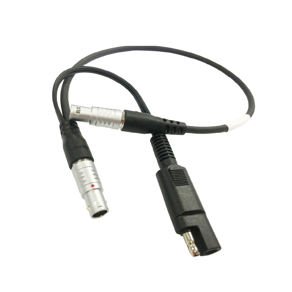
Connectors inside humid, vibration-heavy rigs rarely fail from a single dramatic event. Instead, the plating on contact surfaces erodes in a slow, almost mechanical rhythm. Moisture works its way into microscopic pores, while constant shaking turns each mating cycle into a low-grade abrasion test. Over time, the protective gold or tin layer thins, exposing base metal that oxidizes and develops high-resistance spots. What starts as an occasional signal flicker becomes a field failure that only shows up under load or temperature swings.
The combination of humidity and vibration creates a wear pattern that differs sharply from clean, static environments. Tiny droplets condense inside the connector body, then get vibrated into a slurry with dust and metal particles. That slurry acts like a lapping compound, accelerating plating loss at the exact contact points where current density is highest. Edge areas and wipe zones suffer first, often showing crescent-shaped wear marks or a dull, frosted appearance under magnification. Technicians who rely only on visual inspection frequently miss this because the damage hides below the mating interface.
Field teams dealing with these rigs learn to treat plating wear as a progressive condition rather than a sudden defect. Replacing connectors on a calendar schedule helps, but a better approach is to monitor contact resistance under real vibration profiles and humidity cycles. Some crews also switch to heavier plating thickness or sealed connector bodies with redundant wiping actions. The goal is not to eliminate wear completely—that is unrealistic in a vibrating, moisture-soaked rig—but to keep the wear front from reaching the base metal before the next planned maintenance window.
Impedance Stability After Thermal Cycling and Repeated Mating
Connector impedance rarely drifts in a straight line once assemblies are pushed through thermal cycling. Small shifts in contact normal force, oxide build-up at the interface, and micro-displacement of mating surfaces all leave a signature in the impedance trace. Rather than treating a passing value at room temperature as the final word, it is more useful to track how tightly the impedance stays grouped after the housing expands and contracts over dozens of cycles. The assemblies that hold up best tend to show a brief settling phase followed by a flat plateau, not a slow upward creep.
Repeated mating introduces a second variable that does not always behave linearly. Early cycles may burnish the contact surfaces and temporarily lower impedance, but after enough insertions the plating wears thin and the underlying base metal begins to influence the contact interface. At that point impedance can start to wander with slight changes in insertion depth or lateral alignment. Tight control of the contact spring design becomes critical here; a connector that relies too heavily on plating thickness will look fine after ten cycles and noticeably different after two hundred.
A practical qualification should therefore overlap both stresses rather than running them as separate checks. Thermal cycling followed by repeated mating can expose failure modes that neither test catches on its own, such as a contact beam that loses just enough stiffness to become sensitive to tiny variations in terminal position. Measuring impedance at multiple points through the combined sequence gives a clearer picture of long-term performance than any single pass/fail number. In most cases, stable impedance after both stresses is a better predictor of field behavior than initial contact resistance alone.
Domestic Chinese Connector Lines vs. Export-Grade Builds
Plenty of buyers assume a connector from the same factory is the same part, but domestic-channel batches and export-grade batches often split on contact material, plating thickness, and how much regrind goes into the housing. Export runs are usually locked to an inspection standard, while domestic runs can be quietly cost-reduced after initial qualification. The datasheet readout stays identical; the differences appear later as looser insertion force, higher temperature rise, or faster oxidation in humid air.
Export-grade connectors earn their price in consistency. Across batches, latch tension, insulator color, and mold flash stay within a tighter window. Plating is where the gap becomes easiest to measure: export lots often carry a thicker nickel underplate or heavier gold in the contact area, so salt spray and mixed-gas tests look cleaner. Domestic-channel stock may pass a simple continuity check on day one, but it tends to degrade sooner in vibration, high humidity, or frequent mate/unmate cycles.
That does not make the domestic line inherently bad. For indoor gear that runs dry and sees few plug cycles, standard domestic stock is usually enough. If the product runs continuously powered, gets handled roughly, or needs to meet export certification, the export-grade batch is the safer choice. The practical move is to request two date-coded samples from the same supplier and compare terminal spring tension, housing seam quality, and plating appearance under a loupe. Those details will say more than any printed parameter table.
Marginal Lots That Slip Into High-Reliability Programs
Some lots sit at the edge of a datasheet limit and still pass ordinary outgoing checks. The margins are thin, but the paperwork says they are good. When those same lots get pulled into a high-reliability program, the original pass becomes a fragile assumption: the parts were never characterized for the harsher end-use conditions, and nobody revisits whether the guardband actually holds.
What often goes unnoticed is how the transfer happens. A distributor has leftover inventory, a production line clears a shelf, or a buyer finds a batch with the right part number at a lower cost. The lot gets absorbed into a program that assumes full traceability and stricter screening, yet the supporting data may not include the extended burn-in, thermal cycling, or electrical tests that the end application expects. A device that performs fine in a benign bench setup can drift or fail early once it sits inside a sealed avionics bay or a medical tool that runs around the clock.
The practical safeguard is to treat marginal lots as unqualified until someone proves otherwise. That means checking the original test limits, running a smaller qualification slice under the actual stress profile, and keeping the lot genealogy intact instead of blending it with fully screened material. In high-reliability work, the edge of the datasheet is not a comfortable place to be.
Pre-Order Checks That Cut Field Failure Rates
Most field failures trace back to assumptions made before a single unit ships. A focused pre-order review can catch these early by comparing the actual bill of materials against the approved engineering sample, checking that every capacitor, connector, and firmware image matches the revision that passed qualification. When procurement substitutes a look-alike part or a supplier changes a lot code without notice, that mismatch often becomes a latent defect in the field.
Beyond part verification, running a short functional test at the edge of the specified voltage and temperature range exposes marginal designs that pass at room temperature but fail on a cold morning or in a hot enclosure. It is also worth checking mechanical stack-up tolerances and mating cycles on connectors that were only tested once during prototyping. These checks are inexpensive compared with a product recall or a technician visit.
Finally, capture the results with photos, serial numbers, and measured values instead of a simple pass/fail checkbox. That record makes it easier to trace a later failure back to a specific batch or process change. When each pre-order check is treated as evidence collection rather than a formality, the units that leave the dock are far less likely to return.
FAQ
Spring-loaded contacts absorb tolerance stack and reduce insertion force, but they depend on consistent plunger travel and clean surfaces. Solid pin-and-socket designs tolerate higher current and side loads, which makes them more forgiving in rough handling or frequently reconfigured fixtures.
Hard gold over nickel remains the most common choice because it resists wear and corrosion under frequent cycling. For cost-sensitive programs, selective gold on the contact area with tin on the termination side can work, but mixed-metal contact points need careful compatibility review.
Circular bayonet connectors offer quick locking, better cable strain relief, and proven sealing, so they suit portable field gear. Rectangular high-density types save panel space and simplify multi-signal routing, but they often require additional hardware to reach the same level of vibration resistance.
Contact resistance stability, mating cycle life, operating temperature range, insulation resistance, and shock or vibration ratings should be checked against the actual test profile. Material certifications and plating thickness reports also matter because nominal datasheet values do not always reflect batch-to-batch consistency.
Yes, many suppliers provide IP67 or IP68 circular and rectangular connectors with O-rings and gasket interfaces. However, repeated outdoor mating can wear seals and trap debris, so field tests should include dirty-handling conditions rather than only clean laboratory cycling.
Fretting corrosion, spring relaxation, plating wear, and hairline cracks in housing materials are the most common. Thermal cycling can also produce intermittent opens if the contact retention mechanism relies on a press-fit that loosens over time.
They can when the connector is designed with controlled impedance, proper grounding, and short return paths. A practical approach is to require S-parameter or TDR verification on first articles rather than relying only on the supplier's stated bandwidth.
Look at how the supplier handles pin count changes, keying, cable overmolding, and documentation control. Lead times differ sharply between catalog-first factories and those that build semi-custom assemblies, so the comparison should weigh design support and repeatability over unit price alone.
Conclusion
High-reliability test systems rarely fail because a connector looks wrong on paper. Most problems show up only after thermal cycling, repeated mating, or weeks in a humid vibration rig. Plating wear is a good example: a part that passes initial insertion tests can lose contact force after a few hundred cycles, especially when the test bay runs hot and damp. The datasheet numbers often say nothing about how impedance drifts once the housing relaxes or the spring fingers take a set.
Comparing domestic Chinese connector lines against export-grade builds matters less than checking what actually arrives in the box. Marginal lots do enter high-reliability programs because incoming inspection focuses on dimensions and pinout, not on the plating thickness or the temper of the contact alloy. Pre-order checks that include cross-sectioning samples, running a small thermal and mating cycle before full production, and asking for lot-level traceability have cut field failures in several of our test rigs. If the supplier can’t tell you which plating line and which reel a batch came from, that’s the first sign the “equivalent” option isn’t equivalent where it counts.
Contact Us
Contact Person: Hayley Liang
Email: [email protected]
Tel/WhatsApp: +86 13480625451
Website: https://www.reunion-china.com/